AH 27
Remove the 4 screws from the rear panel, remove the front cover (be cafeful not to loose the springs from the battery cover).
You will see some pads to the left of the channel display.
Solder a bridge across the S 07 pads for 120 channels
(these are on the far left at the top)
OR
Solder a bridge across the S 08 pads for 200 channels
(these are on the top to the right of the S 07 pads)
YOU CANNOT DO BOTH !!!
AH 100
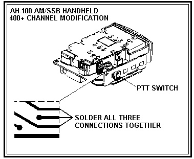
- STEP 1. Remove the battery pack.
- STEP 2. Remove the small philips screw from the side of the case near the
volume control be careful not to lose the hex nut.
- STEP 3. Remove the 3 remaining phillps screws on the backside of the
radio. Carefully remove the battery case lock button (next to the PTT). Be
careful not to lose the small spring inside the battery lock button.
- STEP 4. Carefully remove the back of the radio case. Do not allow the
front side of the cabinet to separate. Keep the internals and the front of
the case together. Remove only the rear of the case.
- STEP 5. Locate and solder all 3 pads (behind the PTT switch) together.
- STEP 6. Carefully replace the rear case and cover. Start all screws but DO
NOT TIGHTEN.
- STEP 7. Install battery lock button with the spring pointing toward the
PTT.
- STEP 8. Press the case closed and tighten all screws.
NOTE:If the case does not close easily check for proper alignment of
plastic parts and battery contact pc.
DO NOT FORCE
- OPERATION OF EXTENDED CHANNELS
CBS 1000
- Remove top cover
- Locate the back of the display board.
- On this board you should see two pin's, Connect a jumper wire between the
pins.
- Power on the Unit holding down the #1 button. Remember to hold the button
down for about 5 seconds after power is applied
- o change bands just press button #1 and the bands are labeled
- A 25.165 - 25.605
- B 25.615 - 26.055
- C 26.065 - 26.505
- D 26.515 - 26.955
- E Does not appear: This is normal 40 CB channels (26.965 - 27.405)
- F 27.415 - 27.855
- G 27.865 - 28.305
- H 28.315 - 28.755
- I 28.765 - 29.205
- J 29.215 - 29.655
CBS 500
- Unplug power source.
- Remove top cover.
-
- Locate the black shorting block on the rear side of the display PCB. Move
the jumper from left to right two pins. Remember to hold the button down for
about 5 seconds after power is applied
- Plug the power source back in.
- Power on the Unit holding down the Channel 9/19 button.
Remember to hold the button down for about 5
seconds after power is applied.
- To change bands just press button #1 and the bands are labeled:
- A 25.165 - 25.605
- B 25.615 - 26.055
- C 26.065 - 26.505
- D 26.515 - 26.955
- E Does not appear: This is normal 40 CB channels (26.965 - 27.405)
- F 27.415 - 27.855
- G 27.865 - 28.305
- H 28.315 - 28.755
- I 28.765 - 29.205
- J 29.215 - 29.655
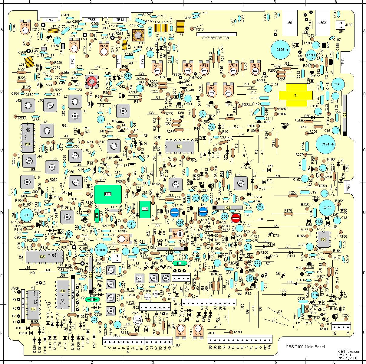
CBS 2010
See Pic for peak-tweak places!
CM 10
- Remove the bottom cover
- Directly behind the M1 button, locate the two capacitors on the front
panel that are not soldered in place.
- Using a very fine tip solder iron attach the two .1uf caps to the pads as
shown in the drawing below.
- Power up the radio and you will now see a band select function above the
M2 button.
- There are 15 bands of 40 channels each.
A, B, C, D, E, -A, -B, -C, -D, -E, +A, +B, +C, +D, +E