Galaxy Freq. Mods!
DX11B
1. Remove the bottom cover of the unit and locate the row of 15 pins along the front edge of the board. Unsolder the wire connected to one of these pins and remove it. Make sure that no other pins are shorted together in this row.
2. Locate the loose wire (usually Purple) in the wiring harness and solder it to the terminal to the left of the Red Wire. Notice that there are two buss wires that connect several terminals together, the Red wire connects to the right side, and the loose wire (Purple) will be soldered to the left side.
3. Locate the MC14008 IC on the circuit board as shown in the diagram above. Unsolder the small solder bridge between pin 16 and the upward extending trace. Be carefull not to short any other pins and make sure that pin 16 is properly soldered to the board. These chips are very static sensitive so if your channels skip around erratically, changing this chip will most likely solve it.
DX22B

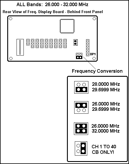
1. Remove the top cover from the unit and locate the 4 pin jumper block on the frequency display board behind the front panel. Move the shorting block from it's current position to obtain the desired frequency range shown in the chart above.
2. Once you have the jumper(s) in place, You must reset the microprocessor by turning the power switch Off. The unit will resume the new frequency range as soon as the power switch is turned on again.
33 HML
1. Remove the top cover from the unit and locate the row of 15 pins across the front of the unit. Unsolder the short jumper wire from the 7th. pin to pins 11 and 12 (connected together).
2. Unsolder the shorting solder bridge of pins 11 and 12 so that they are independent pins having no connection between them.
DX44V
1. Remove the bottom cover from the unit and locate the frequency divider circuit board on the left side of the unit. Remove the screw holding the board and plug in the loose connector on the bottom side.
2. Unsolder and remove the short jumper wire on the top side of the divider board, and re-mount the board back in place.
3. Locate the small 3 pin keyed connector hanging loose near the Band selector switch, and plug it back into it's socket.
DX55V
1. Remove the top cover from the unit and locate the row of 15 pins across the front of the unit. Unsolder the short jumper wire from the 7th. pin to pins 11 and 12 (connected together).
2. Unsolder the shorting solder bridge of pins 11 and 12 so that they are independent pins having no connection between them.
DX66V
1. Remove the bottom cover from the unit and locate the frequency divider circuit board on the left side of the unit. Remove the screw holding the board and plug in the loose connector on the bottom side.
2. Unsolder and remove the short jumper wire on the top side of the divider board, and re-mount the board back in place.
DX73V
1. Remove the bottom cover from the unit and locate the Selector board just behind the Channel Selector. Unsolder and remove the short jumper wire on the rear of the Selector Board.
2. Locate the loose ends of the Gray and Yellow wires coming from the center plug on the Selector Board and Re-Solder them back together. Be sure to use Heat Shrink tubing or any suitable type of insulating material.
3. Locate the small keyed connector plug hanging loose near the Selector Board and plug it back into it's socket as shown in the Diagram above (Purple Wire on the Left).
DX 73V - 10 M Crystal Replacement
Those of you who wish to operate your radios 450KHz higher (28.765-29.205MHz instead of 28.315-28.755MHz) will need to replace the existing 13.560MHz crystal with a 14.010MHz crystal.
77HML
1. Remove the top cover from the unit and locate the row of 15 pins across the front of the unit. Unsolder the short jumper wire from the 7th. pin to pins 11 and 12 (connected together).
2. Unsolder the shorting solder bridge of pins 11 and 12 so that they are independent pins having no connection between them.
DX88HL
1. Remove the bottom cover from the unit and locate the frequency divider circuit board on the left side of the unit. Remove the screw holding the board and plug in the loose connector on the bottom side.
2. Unsolder and remove the short jumper wire on the top side of the divider board, and re-mount the board back in place.
3. Locate the small 3 pin keyed connector hanging loose near the Band selector switch, and plug it back into it's socket.
DX99V
1. Remove the bottom cover from the unit and locate the frequency divider circuit board on the left side of the unit. Remove the screw holding the board and plug in the loose connector on the bottom side.
2. Unsolder and remove the short jumper wire on the top side of the divider board, and re-mount the board back in place.
DX2517

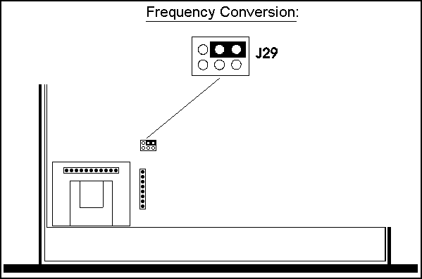
1. Remove the cover from the unit and locate 6 pin jumper labeled J29. Move the shorting block from it's current position to the back/right position as shown.
2. Re-Assemble the unit and check All Bands for Proper operation.
DX2527

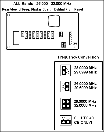
1. Remove the top cover from the unit and locate the 4 pin jumper block on the frequency display board behind the front panel. Move the shorting block from it's current position to obtain the desired frequency range shown in the chart above.
2. Once you have the jumper(s) in place, You must reset the microprocessor by turning the power switch Off. The unit will resume the new frequency range as soon as the power switch is turned on again.
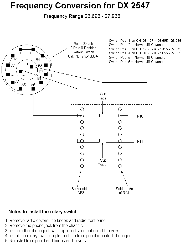
DX2547

Clarifier Modifications:
10 Meter SSB Mobiles
DX 77HML, DX 88HL and DX 99V
|
DX 2517
|
DX 2527
|