Newer Galaxy Radio Peak / Tweak / Freq.
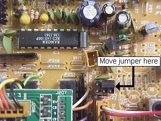
DX45MP:
Freq Conversion:
Move the jumper to the position indicated.
Note the "RCI-145106P" PLL Chip. Ha!
Tune-up:
TX OSC: L23
TX POWER TUNE UP: L40, L42, L43, L44
RF POWER: HI: VR14 LO: VR18
RF POWER METER: VR9
AM MODULATION: VR16
AM MOD METER: VR15
FM DEV: VR5
POT Adjustment Diagram 45MP, 48T:
DX48T:
Frequency Conversion:
Move the jumper to the position indicated.
Tune-up:
TX OSC: L23
TX POWER TUNE UP: L40, L42, L43, L44
RF POWER: HI: VR14 LO: VR18
RF POWER METER: VR9
AM MODULATION: VR16
AM MOD METER: VR15
FM DEV: VR5
SWR Auto Cal: VR1 on EPA010020B
DX73V
Frequency Conversion:
|
1.
|
Remove the bottom cover from
the unit and locate the Selector board just behind the Channel Selector.
Unsolder and remove the short jumper wire on the rear of the Selector
Board as shown above. |
| 2. | Locate the loose ends of the Gray and Yellow wires coming from the center plug on the Selector Board and Re-Solder them back together. Be sure to use Heat Shrink tubing or any suitable type of insulating material. |
| 3. | Locate the small keyed connector plug hanging loose near the Selector Board and plug it back into it's socket as shown in the Diagram above (Purple Wire on the Left). |
Tune-up:
TX OSC: L26
TX POWER TUNE UP: L43,L44,L42,L40,L33
RF POWER: HI: VR13 LO: VR16
RF POWER METER: VR8
AM MODULATION: VR14
FM DEV: VR5
DX73V POT. Adjustment Diagram:
DX93T
Freq Conversion:
before

after
|
1.
|
Remove the top cover from the unit and
locate wire jumper on the bottom of the main pcb. Move the wire from
it's current position to the position shown in the drawing above. |
|
2.
|
Re-Assemble the unit and check All Bands for Proper operation. |
Tune-Up:
TX OSC: LSB-L25;USB-L24;AM-L23
TX POWER TUNE UP: L44,L43,L42,L40 THEN L44 AGAIN for Min SSB distortion.
SSB ALC: VR13
AM CARRIER POWER: HI-VR14;MED-VR911;LO-VR18
RF METER: VR9
AMC: VR16
MOD METER: VR15
FM DEV: VR5
Adjustment Points:
DX95T
Freq Conversion:
before
after
|
1.
|
Remove the top cover from the unit and
locate wire jumper on the bottom of the main pcb. Move the wire from
it's current position to the position shown in the drawing above. |
|
2.
|
Re-Assemble the unit and check All Bands for Proper operation. |
Tune-Up:
TX OSC: LSB-L25;USB-L24;AM-L23
TX POWER TUNE UP: L44,L43,L42,L40 THEN L44
AGAIN for Min SSB distortion.
SSB ALC: VR13
AM CARRIER POWER:
SET RF POWER FULLY CLOCKWISE AND THEN:
VR14 until meter readys 40-50 watts.
SET RF POWER FULLY COUNTERCLOCKWISE AND THEN:
VR18 until meter reads 10-15 watts
RF METER: VR9
AMC: VR16
MOD METER: VR15
MOD LAMP: VR910
FM DEV: VR5
Adjustment locations: