JACKSON MODS
Introduction:
The PRESIDENT JACKSON is a rig of legends, a pure DX
machine based on the Uniden PB042 chassis. Its PLL is the famous MC145106
circuit controlled by IC6 & IC7 (4008 Binary Adders) (See schematic diagram.)
This chassis; by its excellent technical design, will allow a tremendous
collection of modifications, enhancements, alignments .... The PRESIDENT JACKSON
can be considered as a teaching school for beginners and also professionals.
Let's have a quick look at its main and noticeable
specifications:
Channels: 226 AM FM/LSB/USB in its standard export version
25 MHz up to 28,5 MHz when modified.
Frequency Control by PLL
Output Power: 10 W AM / 10 W FM / 21 W PEP SSB
Receiver Sensitivity: < 0.15 microvolts for 10 dB in SSB
Receiver Sensitivity: < 0.50 microvolts for 10 dB in AM
Adjustable Squelch + Automatic Squelch Control System
Adjustable Mic Gain and RF Gain
Double Clarifier
Public Address function
Roger Beep
+10 KHz function
US fantastic MRF477 HF power transistor
AGC Circuit Modification:
Remove C31 (.471mfd) COMPLETELY
Change R43 (10K) to 1k
Change R41 (150k) to 270k
Change R47 (1.5k) to 3.9k
These parts are all located near the rear pins of chip 2902.
UnLock the Fine Clarifier:
Remove diode 58 (found at the extreme
front of radio)
Find the brown wire soldered to back of clarifier and follow it back to the
board.
Remove this brown wire from the board and solder it to the center lead of A473
(found at rear right side of board when speaker side is up and face of radio
towards
Realign radio with L14 for AM, L15 for USB, and Ll6 for LSB.
VCO modification for addition of extra
channels:
1. Cut D26.
2. Replace D27 with Super Varactor Diode
(or Super Slider Diode as it is called). This mod gives extended coverage for
added frequencies. The VCO in the Jackson is good, but becomes unstable as you
add channels, so this mod is highly recommended for those about to add new
frequencies.
3. The new Diode will install exactly as
D27 is removed. Don't accidentally install it backwards.
Note: You will not notice any difference now, but when you do any frequency mods to the unit, it will mean the difference between a mod with all the channels or a mod with only a few new channels.
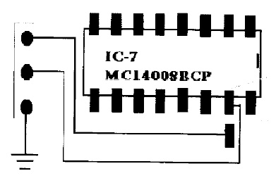
Low Frequency Modification:
1. Cut Circuit board trace at Pin 2 of IC7 or isolate pin 2 from the board.
2. Obtain a SPDT switch and wire per the diagram shown below:
3. With switch on, you will get 25.425
on Channel I up to 25.865 on channel 40 in the A band, and 25.875 on Channel 1
up to 26.045 on Channel 15 in the B band. If these frequencies ARE NOT as
noted, do the following
4. Adjust L12 to bring all the
frequencies back to where they belong. (25.425 MHz on Channel 1 with switch on).
3. Retune RF output at around 26.005 for
good output. NOTE: You will lose around 25% of your power and swing on the low
end of the band. You should adjust power according to where you DX the most.