PEAK-TWEAK and FREQ LC72322-based CBs!
Includes:
Titan II RPSY-485
Magnum 257
Magnum 357
Magnum 457
Pro-Star 400 Mobile
Superstar 4900 Mobile
Hook up radio to power and turn on for a minimum of 10 seconds.
Turn off radio and disconnect from all power sources.
Remove Bottom cabinet cover.
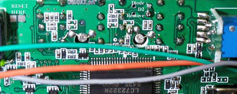
Remove (unsolder) Diode D2. This is the only Non-Surface mount component found in this area.
Reset the radio CPU by temporarily shorting the two front panel circuit board pads located near Just Right of Black Potentiometer.
Hook the radio back up to power and turn on the radio.
Press the FUNC button, then press and hold the CALL button for approx. 3 seconds. The band indicator will appear on LCD.
Use the CALL button to select bands.
To switch between channel and frequency display, press the FUNC button and press the CALL button.
When turned off and on again, the radio will always default to original 10 meter settings. To automatically return to last used frequency and mode, press the FUNC button and then press and hold the CALL button for approx. 3 seconds.
Peak-Tweak:
RV-1 S-Meter Signal Strength
RV-3 FM Deviation
RV-4 AMC, AM Modulation
RV-6 (Unmarked near center of PCB) - Carrier Balance
RV-8 RF Output Meter
RV-9 ALC
RV-11, RV-12 Final Bias Adjustments
RV-13 Driver Bias
RV-14 FM Carrier Power
RV-16 AM Carrier Power
Microphone configuration
Pin Description
1 Audio
2 Receive
3 Transmit
4 Ground = Channel Down, 2.2K ohm to Pin 3 = Channel UP
5 Ground and Switch common
6 13.8 Volts. (NOT current limited!)
WARNING!
DO NOT PLUG A RCI OR OTHER MICROPHONE INTO THIS JACK. THIS COULD RESULT IN
BURNING OUT THE 4.7MH CHOKE FEEDING THE 13.8 VOLTS TO THE MICROPHONE
ELEMENT OR CONNECT 13.8 VOLTS DIRECTLY TO THE CPU! (POOF)
FULL COVERAGE, NO 'Back-To-10M' Conversion:
The down side to this conversion is that the radio can't be toggled back to the 10-Meter only operation and none of the commands associated with this operation can be accessed. The up side is the radio powers on with the last frequency used without the addition steps required in the first conversion. You must decide which is best for your needs.
To perform the full coverage conversion a resistor must be added to the circuit traces shown in the photo below. The diode need not be cut, but if it is already, it won't have any effect on this conversion. The spacing of the pads are for a SMT 1/10 watt resistor. The value required for this conversion is 47KOhms. Good soldering skills are needed to perform this modification. The pads are delicate and will lift off the board with excessive heat. A low wattage small tipped iron is essential. If you choose to use a standard resistor, a 47K 1/8 Watt is preferred for it's small size, but a 1/4 Watt is OK. It's recommended that the circuit traces be followed to other components already attached to them and the standard resistor be soldered to them at those points for added strength. Mounting a standard resistor to the pads meant for the SMD part means the resistor will have to be mounted vertically and the additional stress in mobile operation could and most likely would damage these circuit traces over time with the vibration of the moving vehicle. After the resistor is added and before the power is applied to the radio, short out the two Reset Pads illustrated in the photo below. The conversion is now complete.