Midland Radio
Mods
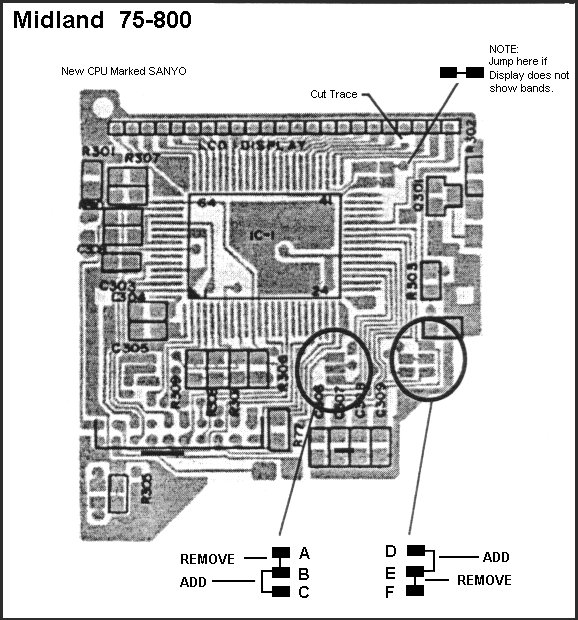
75-800
1.
Remove the case and locate the points ABC & DEF as shown in the diagram.
2. Unsolder the points at locations AB & EF, and solder the points BC &
DE instead.
3.The unit should now operate on the expanded bands. The LCD display will
indicate which band is in use by the designations shown below.
4. The channel 9 button is used for changing band operation.
|
BAND |
LCD DISPLAY |
FREQUENCY RANGE |
|
LOW Band |
"DW" Indicator |
26.515 - 26.955 MHz |
|
MID Band |
"SRF" Indicator |
26.965 - 27.405 MHz |
|
HI Band |
"WX" Indicator |
27.415 - 27.855 MHz |
75-810
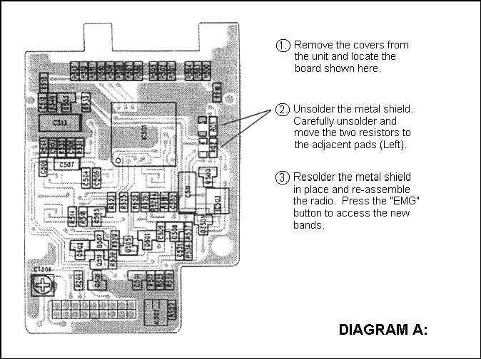
1.
Remove the bottom covers from the unit and locate the Microprocessor circuit
board as shown above. Remember to remove the screws inside the battery
compartment before prying the unit apart.
2. Unsolder and move the two small chip resistors to the adjacent positions just
left of their current position. These Zero Ohm resistors are easily damaged so
be sure to use a low wattage variable temperature soldering iron for the job.
3. Re-assemble the unit and use the "EMG" button to change bands.
Bands are indicated by a small dot in the
upper (HI) or Lower (LO) display window.
77-113/A
1.
Remove the bottom covers from the unit and locate the Microprocessor in the left
front corner of the circuit board.
2. Unsolder the two small solder bridges on the pads shown in Diagram A and
re-solder the adjacent pads as shown
3. Re-assemble the unit and use the "EMG" button to change bands.
Bands are indicated by a small symbol in the Upper (+) or Lower (-) Left side of
the display window.
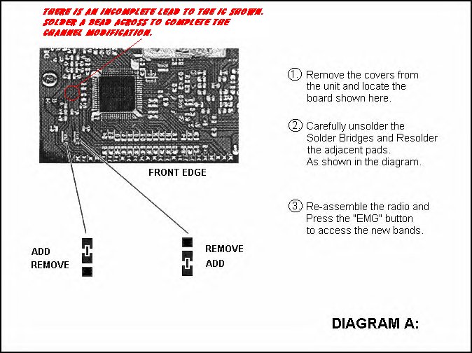
77-115
1. Remove the
covers from the unit and locate the board shown here.
2. Carefully unsolder the solder bridges and re-solder the adjacent pads. As
shown in the diagram.
3. Re-assemble the radio and press the "EMG" button to access the new
bands.
Bands
are indicated by a small symbol in the Upper (+) or Lower on the left side of
the display window.
AMC: Remove resistor below:
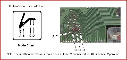
77-255ESP2
| DIODES |
A
|
B
|
C
|
D
|
BANDS
|
|
| 1N4148 |
0
|
0
|
0
|
0
|
40 CH
|
(US & SA Standard CB) |
| 1N4148 |
1
|
1
|
0
|
0
|
40 CH
|
(UK CB Frequencies) |
| 1N4148 |
1
|
0
|
0
|
1
|
120 CH
|
(Polish CB Frequencies) |
| 1N4148 |
0
|
0
|
0
|
1
|
200 CH
|
(Polish CB Frequencies) |
| 1N4148 |
1
|
1
|
1
|
0
|
400 CH
|
(Polish CB Frequencies) |
| 1N4148 |
0
|
1
|
0
|
0
|
120 CH
|
(US and SA Frequencies) |
| 1N4148 |
1
|
0
|
1
|
0
|
200 CH
|
(US and SA Frequencies) |
| 1N4148 |
0
|
1
|
1
|
0
|
400 CH
|
(US and SA Frequencies) |
( The ones and zeroes above represent the presence or absence of a diode at locations A - D )
Installation:
| * | Remove the covers from the radio and locate the microprocessor pads shown in the diagram above. (The pads shown may be under a strip of rubber placed on the circuit board) |
| * | Solder a 1N4148 diode (or 1N914 etc.) into the proper position(s) A through D represented by the frequency chart shown. Choose the desired band(s) of operation and solder each diode into place as indicated by a one on the chart. Positions with zero do not require a diode. |
| * | There is no indicator on the LCD display as to which band the unit is operating on. The channel selector will step up or down into the next band by continuously rotating it past channel 1 or 40. Use the M1, M2, or M3 buttons to store a favorite frequency on one of the extra bands and you will always know which band the unit is operating. Example: M1 = 26.515 Mhz (Ch 1 Lo) M2 = 26.965 Mhz (Ch 1 Normal) M3 = 27.415Mhz (Ch 1 HI) |
| * | To set Memory buttons, select the channel and band, press and hold the memory button for 3 sec. until it beeps twice. your selection will now be stored until the power plug is removed |
77-285/77-285A
1.Remove
the case from the unit and locate the terminals on the circuit board labeled EMG/BAND.
2. Remove the solder from terminals marked EMG, and solder across the terminals
marked band.
3. The unit should now operate on the expanded bands. A small arrow indicator
will designate the band of operation.
4. The channel 19 button is used for changing band operation.
|
BAND |
LCD DISPLAY |
FREQUENCY RANGE |
|
LOW Band |
" |
26.515 - 26.955 MHz |
|
MID Band |
"NO" Indicator |
26.965 - 27.405 MHz |
|
HI Band |
" |
27.415 - 27.855 MHz |
MICROPHONE GAIN MODIFICATION
Chip resistor R138 controls mic gain decreasing the value of the
resistor increases the gain. Generally have 270 ohm, the value can be as
low as 150. If too much gain is used oscillation may occur.
79-290
|
1.
|
Remove from unit. |
|
2.
|
Remove the top and bottom covers. |
|
3.
|
Remove the control head from the unit. The modification will be done inside the control head. |
|
4.
|
Remove the back cover from the control head by removing the four small screws. |
|
5.
|
Refer to the drawing above and make the two solder connections as shown. The two solder connection at the top of the PCB may already be installed. |
|
6.
|
Reassemble the control head. Using a jumper wire short pins 1 and 6 as indicated on the back of the control head to reset the microprocessor, remove the jumper. |
|
7.
|
Test the unit for proper operation. |
|
8.
|
To Access the Expanded Mode of Operation. A. To select 240 channel operation, turn the unit off . hold the "DW" and "CH9" buttons while turning the unit on. You should now see a "D" in the channel display. Pressing the "CH19" Button will cause the unit to cycle from bands "A" through "F" , with band "D" being the normal CB channels. B.
To select the HAM band with high power turn the unit off. Press the "LCR"and
"MIC" buttons while turning the unit on. Release the
buttons and 28.000 should be shown in the display. 170 channels from
28.000 to 29.700 can now be selected with the channel selector. Optimum
performance on the HAM band may require realignment of the trnsmitter and
receiver. To return to normal operation, reverse the
above procedure. If power is lost to the control head or if tile
microprocessor is reset the above functions will have to be reentered. |
MICROPHONE GAIN MODIFICATION
Chip resistor R138 controls mic gain decreasing the value of the resistor increases the gain. Generally have 270 ohm, the value can be as low as 150. If too much gain is used oscillation may occur.