1. Cut trace on PC board between Pin 1 of IC6 and pin 2 of IC4 ( MB3756 ). Next, install a .1uf mylar capacitor at C136 and a jumper wire at J44. This corrects distortion on the SSB transmit audio:
2. Bypass or install a jumper across resistor R180. This resistor limits available current to bias regulator transistor TR37 and causes final bias to go negative and limits power output and increases distortion.
3. Install a 100 ohm - 1/4 watt resistor from pin 12 of IC5 to ground. This increases the gain of the transmit mixer and is necessary when you do frequency expansion mods.
4. Change capacitor C163 to 3pf. This improves bandwidth of transmit bandpass filter. Change C41 to 3pf. This improves bandwidth of the receiver bandpass filter. These changes are necessary to provide uniform performance over a wide range of frequencies on transmit and receive.
5. Remove capacitor C174. Install a 1000 uf, 25V capacitor, negative lead to negative side of C174 (on PC board) and positive lead to base of transistor TR41. Change TR41 to a 2N6487. These changes make a tremendous improvement to AM transmit audio and modulation.
6. To tie clarifier on transmit and receive, remove diodes D52 and D75. Disconnect green wire that goes from R44 to Rx 8 volt source at Rx 8 volt end (near front of PC board ). Reconnect to continous 8 volt source.
7. To modify clarifier for maximum frequency range on transmit and receive, remove diodes D44, D75, and D51. Next remove resistors R44, R174, and R149. Move blue wire that comes from center leg of voice lock to cathode side of D51 ( on PC board ), and move orange wire that comes from top of voice lock to continous 8 volt source. Adjust L22, L23 and L59 to frequency with voice lock set to the 12 O'clock position.
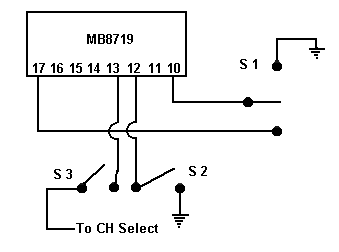
8. There are several ways to modify these radios for expanded frequency operation.
a. The simplest way is to install 2 SPST switches, connect them to pins 10 and 12 of PLL IC and ground. This will give you coverage from 26.815 to 28.045 mHz.
b. The other way is to use a SPDT center off switch and connect as follows:

Resistor R95 must be removed and R99 needs to be changed to a 30K ohm.
With the 11.325 mHz crystal, frequency coverage is 26.815 mHz to 28.725 mHz .
With the 11.1125 mHz crystal, frequency coverage is 26.175 mHz to 28.085 mHz .
Total number of channels is 192.