Frequency Expansion
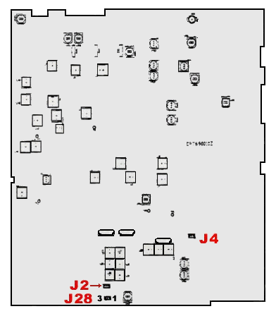
1. Find J28. (forward edge, center of main PCB).
2. Move jumper from pins 1-2 to 2-3.
3. Find J4 (about 2 inches behind mike jack, 2 inches back from fws edge of main pcb ).
4. Unplug blue-black-white plug, and plug into J2 ( near J28 ).
NOTE: This should only plug in one way: ( blue wire to left )
5. Change 3 position band switch to 6 position switch ( on TR-6900 Series only )
6. The Hi-Low tone switch on front panel now becomes the Hi-Low band switch to give 12 bands of 40 channels, totaling 480 channels available.

| BAND | Low Frequency Pool | High Frequency Pool |
| A | 24.265-24.705 | 26.965-27.405 |
| B | 24.715-25.155 | 27.415-27.855 |
| C | 25.165-25.605 | 27.865-28.305 |
| D | 25.615-26.055 | 28.315-28.755 |
| E | 26.065-26.505 | 28.765-29.205 |
| F | 26.515-26.955 | 29.215-29.655 |
Frequency Expansion
1. Find J28. (forward edge, center of main PCB).
2. Move jumper from pins 1-2 to 2-3.
3. Find J4 (about 2 inches behind mike jack, 2 inches back from fws edge of main pcb ).
4. Unplug blue-black-white plug, and plug into J2 ( near J28 ).
NOTE: This should only plug in one way: ( blue wire to left )
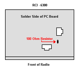
5. On the solder side of the main PCB, remove the 100 ohm resistor between pins 15 and 16 of IC5.
NOTE: Re-check the green wire from the main PCB to J301 of channel selector PCB for connection. This wire may have come off during the process of removing this resistor. If the wire is off or loose, sometimes when the BRT/DIM switch is depressed, the frequency will change instead of adjusting the back lighting.
6. The Hi-Low tone switch on front panel now becomes the Hi-Low band switch to give 12 bands of 40 channels, totaling 480 channels available.
7. To prevent the digital frequency display from "jumping", the VCO (steering voltage) MUST BE re-aligned. Disconnect the "short PCB" from TP7, TP8, and TP9. Set radio to Fr Pool 6, CH 40 AM RX mode, set the +10KHz switch to OFF position, connect multimeter to TP2, connect oscilloscope to TP3. Adjust L14 for 6.5 Vdc ± 0.1. Adjust L15 for maximum output and balance ( CH1 & CH40 ).
8. Reconnect the "short PCB" from TP7, TP8, and TP9.
 |
 Location of resistor in step 5. ( applies only to RCI-6300 ) |
| BAND | Low Frequency Pool | High Frequency Pool |
| A | 24.265-24.705 | 26.965-27.405 |
| B | 24.715-25.155 | 27.415-27.855 |
| C | 25.165-25.605 | 27.865-28.305 |
| D | 25.615-26.055 | 28.315-28.755 |
| E | 26.065-26.505 | 28.765-29.205 |
| F | 26.515-26.955 | 29.215-29.655 |
Frequency Expansion
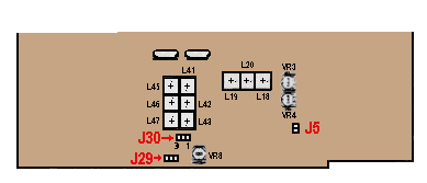
1. Find J30. (forward edge, center of main PCB).
2. Move jumper from pins 1-2 to pins 2-3.
3. Find J5 (about 2 inches behind mike jack, 2 inches back from fws edge of main pcb ).
4. Unplug blue-black-white plug, and plug into J29.
NOTE: This should only plug in one way: ( blue wire to left )

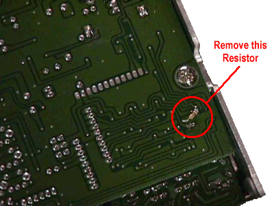
5. On the solder side of the main PCB, remove the 100 ohm resistor.

Location of resistor in step 5.
6. The Hi-Low tone switch on front panel now becomes the Hi-Low band switch to give 12 bands of 40 channels, totaling 480 channels available.
7. To prevent the digital frequency display from "jumping", the VCO (steering voltage) must be re-aligned. Disconnect the "short PCB" from TP7, TP8, and TP9. Set radio to Fr Pool 6, CH 40 AM RX mode, set the +10KHz switch to OFF position, connect multimeter to TP2, connect oscilloscope to TP3. Adjust L14 for 6.5 Vdc ± 0.1. Adjust L15 for maximum output and balance ( CH1 & CH40 ).
8. Reconnect the "short PCB" from TP7, TP8, and TP9.
Echo Adjustment -
The RCI-6900 series does not provide echo adjustment from the front panel. This is because of the addition of course/fine tune controls for SSB operation.
1. With the radio front facing you, remove cover.
2. The echo board is on the right side, underneath a metal cover.
3. Remove metal protective cover.
4. The left pot is for time adjustment, the right pot is for duration.
5. Adjust as desired.
6. To totally disable echo, turn left pot fully clockwise. ( This will eliminate all echo effect when transmitting )