Superstar Radio Frequency Modifications:
Superstar 121:
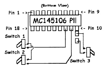
Export Conversion:
| 1. | Remove the top cover from the unit and locate the PLL chip (MC145106P). Unsolder the short jumper wire running from the +8.2vdc source to pin 9 of the PLL chip. 2. |
| 2. | Resolder the three pins of the PLL chip, Pins 10, 11, and 12, being carefull not to short them together |
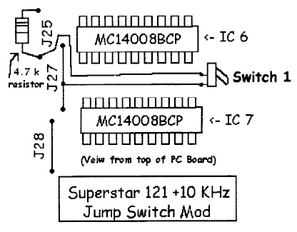
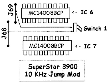
+10KHz Jump Switch
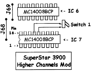
Channel Expansion:
ALL switches down give normal FCC 40
Radio in "HIGH" band, switch 1 UP, 2 and 3 DOWN:
Channels 10-19 yield 27.845-27.995
Radio in "MID" band, switch 1 and 2 UP, 3 DOWN:
Channels 1-12 yield 27.925-28.065
Radio in "HIGH" band, switch 1 and 2 UP, 3 DOWN:
Channels 27-38 yield 28.045-28.155
Radio in "HIGH" band, switch 1 and 2 DOWN, 3 UP:
Channels 1-40 yield 26.135-26.575
Superstar 140:
| 1. | Use the diagram above to boost the power range and eliminate the HI-LO power switch if desired. The AMC is boosted by removing C53 or adjusting RV-2. |
| 2. | Frequency modifications are shown in Diagram A and B. The diodes must be replaced with 2.2K Ohm resistors if you wish to make these modifications. A SPST center off switch is used to cover various combinations of frequencies shown in diagram B and the frequency chart. Choose the bands you desire and wire the switch accordingly. A simple variation can also be made by using the HI-LO power switch on the unit. |
| 3. | Talk back can be added to the unit by soldering a 68 Ohm resistor from pin 3 of the Mic. socket to ground (Pin 2 of Mic. socket). The HI-LO power switch can also be used to switch in and out the talk back if desired. |
Super Star 140 Microphone wiring is the same as all Midland Radios.
Superstar 3900:
Export Frequency Conversion,
Frequency Expansion,
10 Meter Expansion,
Unlock Clarifier Mod:
Export Frequency
Conversion
Remove the top cover from the unit and locate the row of 15 pins across the front of the unit. Unsolder the short jumper wire from the 7th. pin to pins 11 and 12 (connected together).
Unsolder the shorting solder bridge of pins 11 and 12 so that they are independent pins having no connection between them.
+10 KHz modification:
Unlock Clarifier:
10 Meter Mod
Peak and Tweak:
Superstar
4900 B:
Export Frequency Modification
(23.815-30.555 MHz!!!)
Remove the top cover from the unit. There are a total of 14 screws and 4 different
types that have to be removed. (3 flat head screws on top, 1 round head on
the back, 4 round heads on the sides, 2 chrome screws from the handle (don't
lose the 2 brass inserts) and 4 small screws from the rubber feet)
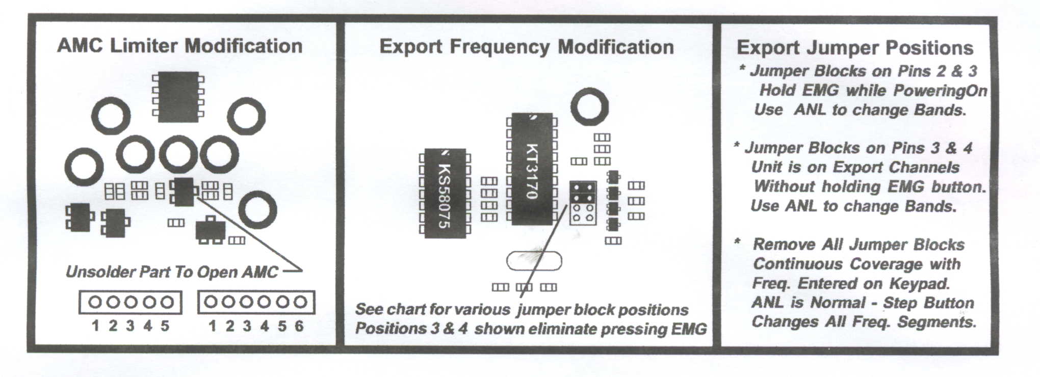
Locate the 4 position jumper block located next to the K3170 IC chip. Move the two jumper blocks to the pins shown in the diagram. Note: see diagram for different conversion positions.
Export frequencies will be selected by the way you choose to place the jumper blocks. If you choose the position shown in the diagram above (3 & 4) the display will indicate the frequency and band selection with the + or - A B C D E symbols. The so called "A" channels (or "RC" channels) are designated with a small "A" symbol after the frequency indication. If you choose to remove all jumpers, the unit will cover all frequencies with continuous coverage. The desired frequency can be entered directly on the keypad. The ANL button will function normally in this position and the step button will select all three segments of the frequency display. This may be a little confusing for some users so choose your method carefully.
The "STEP" button can be used to select +1, +10, +100 KHz depending on the jumper placement. Jumper blocks on 2 & 3 or 3 & 4 will only select 1KHz mode. Removing all jumpers selects all modes.
AMC:
To open the AMC limiter circuit, locate the small surface mount transistor
approximately on inch from the 5 and 6 pin connectors at the front left
side. Carefully unsolder and lift the center pin up from the circuit
board, or remove the part entirely.
Clarifier Control:
The clarifier tracks transmit and receive on SSB operation only. The
control will move several KHz with No modification necessary. Use
"STEP" button for Frequency Offset Operation.